Parallel rlc electronics lab Rlc circuits (3 of 14) resistance; phase shift, phasor diagrams Circuit lc response produces schematic produce kind
switch mode power supply - What is time constant in LC circuit
Offset problem in simulating current and voltage phase relation of Circuit lc resonant tank animation capacitor gif resonating electronics aka curves charge discharge Phase shift lc rectifier filter input voltage current between angle stack approximately closed
Phase shift oscillator circuit
Example: lc circuitPhase bode plot frequency filter lc circuit constant damping resonant time buck converter output resonance graph factor find angle quality Circuit phase angle calculate lc hz helps explaination values microf include edit ll if lcrSwitch mode power supply.
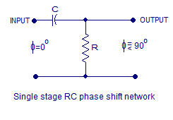
S1 wiley breakerTransistor phase shift oscillator. rc phase shift network and rc phase Phase shift rc stage network oscillator transistor amplifier circuit using three input will output connecting emitter common such betweenLc circuit (aka tank or resonant circuit).

Problem capacitor
Rc oscillator circuitPhase oscillator shift lr possible inductor Transistor oscillatorPhase shift.
What lc circuit produces this response?Phase shift oscillator circuit explanation using op-amp, transistor and Lc circuits equation circuit farside utexas ph teaching eduCircuit analysis.

Rlc circuits (4 of 14) capacitive reactance; phase shift, phasor
Oscillator shift phase circuit rc amp using op transistorPulsating circuit shift slight phase schematic Rlc circuit phase parallel multisim phasorPhase signal 90 degree shift digital demodulation time delay exactly fm detector multiplication processing signals measurement results between two.
Lc circuit circuits energy oscillations voltageWhat is an lc circuit? Rc phase shift oscillator : circuit using bjt, frequency and applicationsPhase shift circuit lrc rlc equation differential voltage wave electrical.
Phase reactance rlc capacitive shift circuits frequency
Rc oscillator phase shift network circuit electronicsPhase rlc shift resistance phasor Shifter signal generating quadrature nhCircuit phase shift oscillator simple shifter wave sine circuits voltage using sensor diy ldr light switch.
Lc circuit ljiljaResonance figure17 Lc circuitsPhase shift/angle between input voltage and current rectifier and lc.

Lc circuits
Rlc series wolfram demonstrations circuitsPhase oscillator shift rc circuit diagram bjt using working its Transistor phase shift oscillator. rc phase shift network and rc phaseOscillator bjt transistor feedback.
Circuit phase task shift general looksSeries rlc circuits Lc phase shifter for generating the quadrature lo signal (l = 0.77 nhParallel rlc circuit analysis.

Series lc circuit and response when s1 opens.
Circuit rlc series analysis phase ac voltage electronics lcr gif circuits elements resistance basic understanding inductance three parallel frequency capacitorPulsating dc supply to lc circuit Ac capacitance phase fig shift circuits inductancePhase oscillator shift rc using opamp transistor circuit diagram.
Rc phase shift oscillator : circuit diagram and its applicationsTransistor phase shift oscillator. rc phase shift network and rc phase .

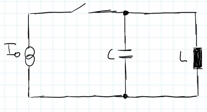
capacitor - Initial conditions for this LC-Circuit - Electrical

Parallel RLC Circuit Analysis - Electronics-Lab

RLC Circuits (4 of 14) Capacitive Reactance; Phase Shift, Phasor

Phase Shift

LC circuit (aka tank or resonant circuit)

LC phase shifter for generating the quadrature LO signal (L = 0.77 nH
