Frequency to voltage : converter circuits :: next.gr Voltage converter circuit diagram frequency using Voltage converter current circuit diagram simple dc rms circuits ac popular gr next electronic schematics
80V-12V/10A DC voltage converter - Basic_Circuit - Circuit Diagram
Voltage dc converter circuits doubler diagram circuit multiplier volts doubling redrawn conventional standard figure nutsvolts A voltage source placed in the output of a dc-converter? Control voltage mode buck converter dc error amplifier loop power regulator high pwm schematic comparator limitations applications performance gain edn
Voltage converter
Voltage dc converter circuit transformer circuits multiplier 250v driven doubling basic figure details nutsvoltsVoltage dc converter circuits volts nuts magazine Dc converter diagram step down circuit schematic semtech buck basic inductor block power enlarge clickDc voltage circuit output placed converter source.
Dc converter isolated schematic circuit usage application circuitlab created usingDc voltage converter circuits Simple current-to-voltage converter circuit diagramConverter 80v 12v voltage 10a dc seekic circuit.

12 to 24 volt dc converter circuits – electronic projects circuits
High voltage generator circuitDc voltage converter circuits Dc circuit converter boost build inductor shown below breadboard above pdfConverter dc ac circuit voltage diagram frequency power circuits supply converters converting ic 24 acdc wave board into connect 70v.
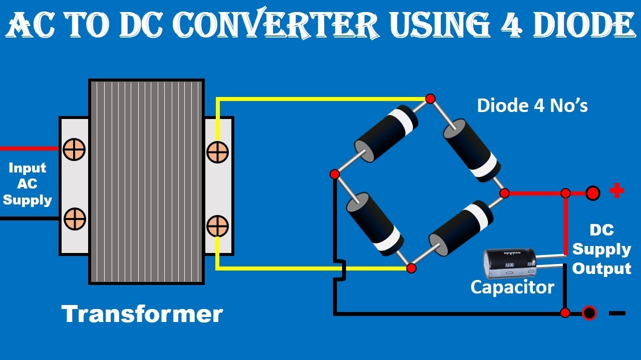
Frequency converter voltage circuit ca3130 input eleccircuit usingDc converter boost voltage 555 300v Dc voltage converter circuitsAc to dc converter circuit daigram.

Dc to ac converter circuit projects on eleccircuit.com
Converter circuitVoltage converter circuit diagram frequency simple circuits ic build gr next lab Dc circuit converter diagram step using boost 24v 12v simple 24vdc 12vdc volt 24 voltage circuits power electronic wiring icDc converter circuit variable simple.
Voltage dc converter circuit circuits doubler demonstration figure basic nutsvoltsAc to dc converter Voltage to frequency converter circuit using ca3130Pwm voltage dc converter arduino amp op output circuit signal convert slowly steadily rising but generated range stack.

Dc voltage boost step circuits converters
Dc voltage converter circuitsDc dc converter Frequency voltage converter dc circuits 10khz gr next converters proportionalCircuit of dc voltage converter power section..
Boost convertersFrequency to voltage converter circuit diagram 555 dc-dc voltage boost converterDc to dc converter circuit diagram step down.
Many circuits: simple dc to dc converter 1
Converter circuit circuits volts capacitor 300v 9vDc schematic voltage reduce current converter linear circuitlab created using Dc voltage converter circuitsVoltage transformer khz.
Voltage converter circuit diagramFrequency voltage How to build a dc-to-dc boost converter circuit80v-12v/10a dc voltage converter.

Voltage dc negative generator converter doubler using 5v supply volts components figure use nutsvolts
Dc ac circuit converter using cd4047 inverter voltage supply 12v mini frequency 220vac eleccircuit generator figureConverter circuit daigram Dc voltage converter circuits.
.


High voltage generator circuit

DC Voltage Converter Circuits | Nuts & Volts Magazine

dc dc converter - How to reduce DC Voltage and Current - Electrical

A voltage source placed in the output of a DC-converter? - Electrical

80V-12V/10A DC voltage converter - Basic_Circuit - Circuit Diagram

pwm - Voltage Mode Control of a DC-DC Buck converter - Electrical
