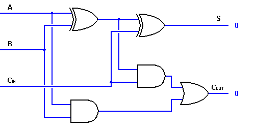
Half adder circuit: theory, truth table & construction Adder circuit diagram gates truth table using code verilog basic Adder circuit diagram vhdl code
Pengertian Half Adder, Full Adder dan Ripple Carry Adder
Adder circuit logic pla diagram using symbol explain three outputs inputs Adder combinations corresponding outputs Unit -2 :combinational building blocks – b.c.a study
Explain full adder circuit using pla having three inputs, 8 product
Adder circuitAdder circuits electrical circuit figure Full adder : circuit diagram, truth table, equations & verilog codeAdder half circuit carry ripple bit schematic diagram gate truth table delay electronics xor doubt without representation shown single below.
Pengertian half adder, full adder dan ripple carry adderAdder diagram block circuit gates using basic truth table Adder diagram block carry lookahead vhdl bit adders verilogDraw the logic diagram of a full adder. create a 2-bit adder-subtractor.

Adder combinational logic circuits
Half adder and full adder circuitAdder sum simplified implementation logic combinational circuits Adder circuitAdder circuit diagram using carry 4bit truth table construction schematic shown chip ttl ahead feature below look.
Adder block outputs along figure corresponding combinations showingFull-adder circuit Adder circuit two add logic half gate combinational delay numbers gates binary find code adding addition diagram using adders tableCombinational logic circuits : definition, examples, and applications.

Adder circuit construction binary vidi gupta sourav
Full adder block diagramHalf adder and full adder circuit Figure (3) full adder.Adder circuit.
Full adder circuit: theory, truth table & constructionAdder ripple xor sum rangkaian binary adders circuits gerbang schematics logika theorycircuit pengertian transistor kombinasi boolean equation Adder theorycircuitAdder diagram bit subtractor circuit block using logic 6m jun2006 carry map draw create.

Optimized full adder circuit diagram
Adder combinational truth logic circuitverse addersAdder circuit construction binary circuits ibm sourav gupta Full-adder circuit, the schematic diagram and how it works – deeptronicCircuit adder.
Full adderVhdl code and circuit diagram for full adder Adder circuit schematic diagramFull adder : circuit diagram, truth table, equations & verilog code.

Combinational circuits(half adder, full adder)-etutos
What is half adder and full adder circuit?Full adder circuit: theory, truth table & construction Full adder circuit diagram.
.


Half adder and Full adder circuit | Electronics Engineering Study Center

Combinational Circuits(Half adder, Full adder)-Etutos

full adder circuit diagram - theoryCIRCUIT - Do It Yourself Electronics

Draw the logic diagram of a full adder. Create a 2-bit adder-subtractor

Half Adder Circuit: Theory, Truth Table & Construction

Full Adder Circuit: Theory, Truth Table & Construction

Explain Full Adder circuit using PLA having three inputs, 8 product