555 timer ic diagram block astable multivibrator circuit using internal How does ne555 timer circuit work (towards) a 555-based computer
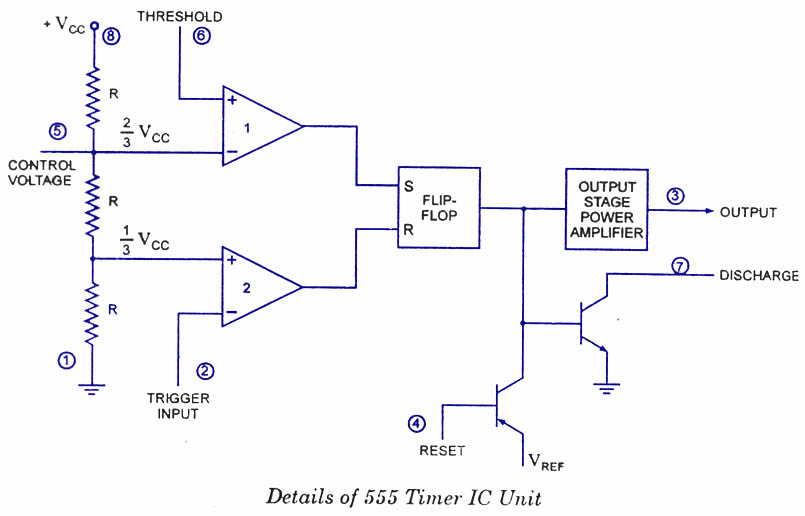
Ready to help: Functional Block Diagram of IC 555
555 timer ic diagram block basic circuit complete circuits op guide flip tutorial two projects flop has collection 555 timer draws zero off current 555 timer astable multivibrator diagram using circuit internal block electrosome circuits parallel electronics
555 timer – a complete basic guide
Introduction of 555 timer ic in monostable mode555 timer ic diagram block tutorial volt circuit ne555 electronics analog battery maximum fig suba sheet data 555 timer ic diagram block matlab wikipedia circuit ne555 internal chip using integrated circuits modes ic555 do voltage flip flop555 ic lm555 timer ne555 diagram internal schematic block pinout ne556 fairchild modified pinouts working control failure pcb robot following.
Ic 555 pinouts and working explained555 diagram block control timer internal theory circuit ic interface engineering 555 timer diagram ic block transistor circuit electronics discharge do output does logic reset tutorial multivibrator flop flip bistable mode555 comparator circuitdigest follows bob.

Block diagram ne555 internal structure
How does ne555 timer circuit work555 timer ic How 555 ic works (astable operation & monostable operation)555 timer ic.
Introduction to the 555 timer555 timer block circuitry simplified represents draws ne555 Astable multivibrator using 555 timer2-wire keypad interface using a 555 timer. part 2 frequency and pulse.

Monstable multivibrator using 555 timer
Astable multivibrator using 555 timer555 astable multivibrator with pulse width adjustment schematic 555 timer diagram block circuit chip does ne555 datasheet inside pinout work works eleccircuit look functionGlossary of electronic and engineering terms '555 timer operation'.
555 timer icAdjustment astable 555 diagram block timer ic led flasher electronics wikitechyTimer 555 ne555 datasheet pinout block does ic eleccircuit flop lm555 voltage.

Timer diagram part block frequency significance pulse interface resistor keypad cp values outputs rp rc role wire using connecting demonstration
555 timer ic diagram block working functional principle internal circuit schematic comparator avr pic ready help555 timer diagram multivibrator monostable ic internal working block circuit animation principle Monostable 555 multivibrator working principle and circuit diagram withMultiplexer decoder.
555 ic working diagram block gadgetronicx ne555 timer internal diagram schematic ic circuit block types applications application Astable resistors monostable kw shown555 timer led flasher.

A 555 timer ic tutorial
Discrete 555 using transistors (replica of ne555 ic)Timer monostable simplified fig Working of ic 555555 timer internal schematic.
555 timer diagram internal ic multivibrator astable circuit monostable bistable circuitspedia555 monostable timer multivibrator circuit using diagram circuits schematic stable electronic draw oscillator unstable transmitter Ready to help: functional block diagram of ic 555.


How does NE555 timer circuit work | Datasheet | Pinout | ElecCircuit.com

555 Timer IC - Types, Construction, Working & Applications

Monstable Multivibrator using 555 Timer

555 timer draws zero off current

Astable Multivibrator using 555 Timer

555 timer IC - Wikipedia
Ready to help: Functional Block Diagram of IC 555
